简体中文
简体中文 English
 русский
 Español
 Français
 عربى
عربى Português
 日本語
日本語 italiano
 Nederlands
 Polskie
Content
- 1 The Physics of Pipe Bends
- 2 90-Degree Elbow: Compact and Direct
- 3 45-Degree Elbow: Flow-Optimized Routing
- 4 Pressure Drop Comparison: K-Values and Equivalent Pipe Length
- 5 Space Layout and Installation Considerations
- 6 Application Guide by Industry
- 7 When to Use Two 45-Degree Elbows Instead of One 90-Degree Elbow
- 8 Decision Checklist: 90° or 45° Elbow?
The Physics of Pipe Bends
Every time a pipe changes direction, the fluid inside must decelerate, turn, and re-accelerate. That process consumes energy. The sharper the turn, the more turbulence is generated, the greater the pressure drop, and the more work the pump or system pressure must do to maintain flow. This is not a minor detail in a well-engineered system—it is a quantifiable cost that accumulates across every fitting in the network.
The choice between a 90-degree elbow and a 45-degree elbow is fundamentally a choice between two different tradeoffs: spatial compactness versus hydraulic efficiency. A 90-degree elbow completes a right-angle turn in the shortest possible linear distance. A 45-degree elbow directs flow along a more gradual arc, reducing turbulence at the cost of more space and, in some layouts, more fittings. Neither is universally better. The right answer depends on the system's pressure budget, the available installation space, and the material flowing through the pipe.
Pipe fittings are standardized under dimensional and performance standards such as ASME B16.9 for factory-made butt-welding fittings, which governs the geometry, wall thickness, and material specifications that define how these elbows perform under pressure.
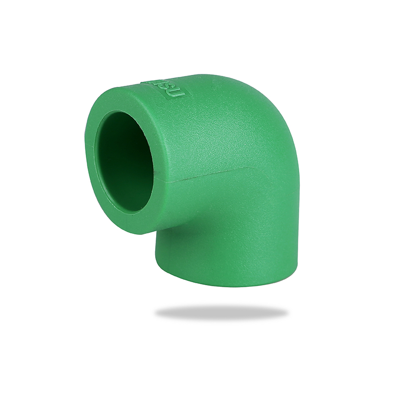
90-Degree Elbow: Compact and Direct
A 90-degree elbow redirects flow through a full right angle in a single fitting. Its defining characteristic is spatial efficiency: the footprint required to complete a 90-degree direction change with one fitting is substantially smaller than any multi-fitting alternative. In confined mechanical spaces, building service shafts, or equipment rooms where pipe routing must navigate around structural elements, this compactness is the primary reason 90-degree elbows are specified.
The hydraulic cost is turbulence. As fluid enters the elbow, the abrupt change in direction creates a separation zone on the inner radius of the bend, where flow detaches from the pipe wall and forms recirculating eddies. These eddies increase resistance, generate noise in liquid systems, and in gas systems can cause localized pressure fluctuations. At low flow velocities, the effect is minor. At high velocities or in systems where the fluid carries suspended solids or entrained particles, the impact zone on the outer radius of the 90-degree elbow wears measurably faster than the straight pipe sections.
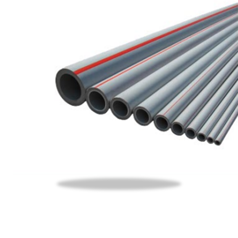
90-degree elbows come in two radius variants: short-radius (SR), where the centerline radius equals the nominal pipe diameter, and long-radius (LR), where the centerline radius is 1.5 times the nominal diameter. Long-radius 90-degree elbows significantly reduce the pressure drop compared to short-radius by distributing the directional change over a longer arc. Wherever space allows, long-radius is preferred for flow-critical applications. Our PPR pipe elbows and fittings include both standard and long-radius 90-degree configurations for building water supply and heating systems.
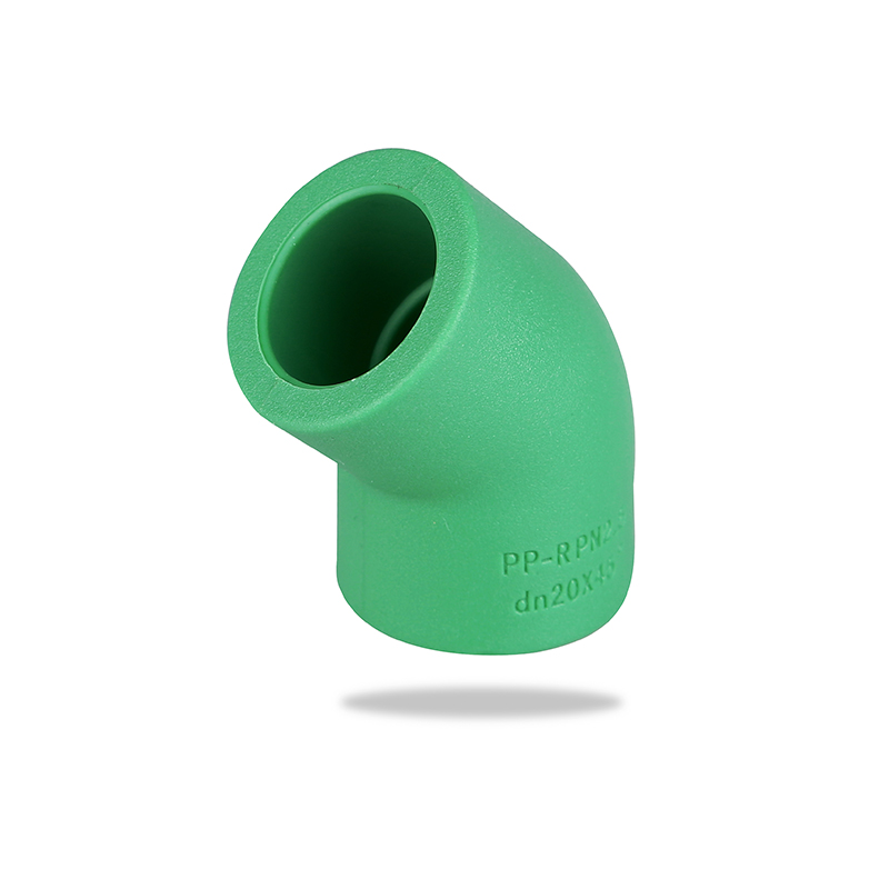
45-Degree Elbow: Flow-Optimized Routing
A 45-degree elbow changes flow direction by half of what a 90-degree elbow does, using a shallower arc that keeps fluid velocity vectors closer to the original flow path. The result is less abrupt deceleration, smaller separation zones on the inner radius, and significantly lower pressure drop. The fluid "sees" a gentler transition, retains more of its kinetic energy through the bend, and emerges with less turbulence on the downstream side.
This makes 45-degree elbows the preferred choice wherever flow efficiency is the primary design driver—HVAC ductwork, chemical processing lines, water treatment distribution, and high-flow industrial systems where cumulative pressure loss across multiple fittings affects pump sizing and operating cost. Reducing pressure drop at every fitting reduces the pump head required to maintain target flow rates, which directly reduces energy consumption over the life of the system.
The spatial tradeoff is real. A 45-degree elbow alone only changes direction by 45 degrees, so reaching a full 90-degree turn requires either two 45-degree elbows with a connecting pipe section between them, or one 45-degree elbow combined with diagonal routing in the layout. Both approaches require more linear space than a single 90-degree elbow—a consideration that matters in dense equipment arrangements and is often irrelevant in open ceiling runs or outdoor above-ground installations.
One often-overlooked maintenance advantage of the 45-degree elbow: its lower-velocity impact zone means the outer radius wears more slowly. In slurry service, abrasive media transport, or any system where erosion is a design constraint, the 45-degree elbow's longer service life between replacements reduces lifecycle maintenance costs.
Pressure Drop Comparison: K-Values and Equivalent Pipe Length
Engineers quantify the hydraulic resistance of fittings using the K-value (resistance coefficient), which represents the number of velocity heads lost as fluid passes through the fitting. The pressure drop is then calculated as:
ΔP = K × (ρv² / 2) — where ρ is fluid density and v is flow velocity.
Standard K-values for common elbow types under turbulent flow conditions:
| Fitting Type | Typical K-Value | Equivalent Pipe Length (×D) | Relative Pressure Loss |
|---|---|---|---|
| 90° Short-Radius Elbow | 0.9 – 1.5 | 30 – 50 pipe diameters | Highest |
| 90° Long-Radius Elbow | 0.4 – 0.7 | 16 – 25 pipe diameters | Medium-High |
| 45° Standard Elbow | 0.2 – 0.4 | 8 – 16 pipe diameters | Low |
| Two 45° Elbows in Series | 0.4 – 0.8 | 16 – 32 pipe diameters | Medium (comparable to LR 90°) |
The equivalent pipe length concept is useful for system designers: a standard 90-degree short-radius elbow in a DN100 pipe (100 mm diameter) produces roughly the same pressure drop as 30–50 meters of additional straight pipe. In a system with ten such elbows, that represents up to 500 meters of equivalent pipe resistance added to the network—significant enough to influence pump selection and operating cost calculations.
A 45-degree elbow under the same conditions adds only 8–16 equivalent pipe diameters, approximately one-third to one-half the resistance of the short-radius 90. In pressure-sensitive systems, this difference is the engineering basis for specifying 45-degree elbows wherever the layout permits.
Space Layout and Installation Considerations
The spatial footprint of the two elbow types differs in a way that affects layout planning before a single fitting is purchased. A 90-degree elbow completes its turn within a very short offset distance—the fitting itself provides the full directional change. A 45-degree elbow requires a diagonal pipe run between two fittings (or an offset routing path) to achieve the same net directional change.
For vertical-to-horizontal transitions in building services—such as a riser dropping into a horizontal distribution header—the 90-degree elbow's compact geometry is often the only practical option given structural constraints. The fitting fits within a standard floor void or wall cavity without requiring diagonal coordination with other services.
For horizontal routing around obstructions or through open ceiling spaces, the diagonal run made possible by 45-degree elbows is frequently the cleaner solution: fewer fittings overall, more gradual direction changes, and a layout that accommodates future modifications more easily than a grid of 90-degree turns.
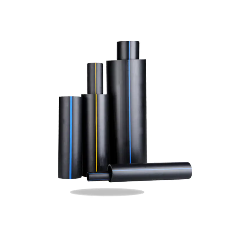
PPR and HDPE plastic pipe systems have an additional consideration: thermal expansion. Plastic pipes expand and contract with temperature changes more than metal. Systems designed with intentional offsets using 45-degree elbows can absorb axial expansion through the flexibility of the diagonal run, reducing stress on fixed supports and joints compared to a rigid 90-degree grid layout.
Application Guide by Industry
The optimal elbow angle varies significantly by system type. The following recommendations reflect the balance of hydraulic performance, space constraints, and operational requirements typical in each sector:
| Application | Recommended Elbow | Primary Reason |
|---|---|---|
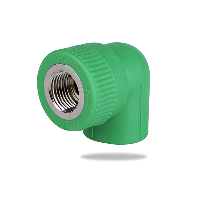
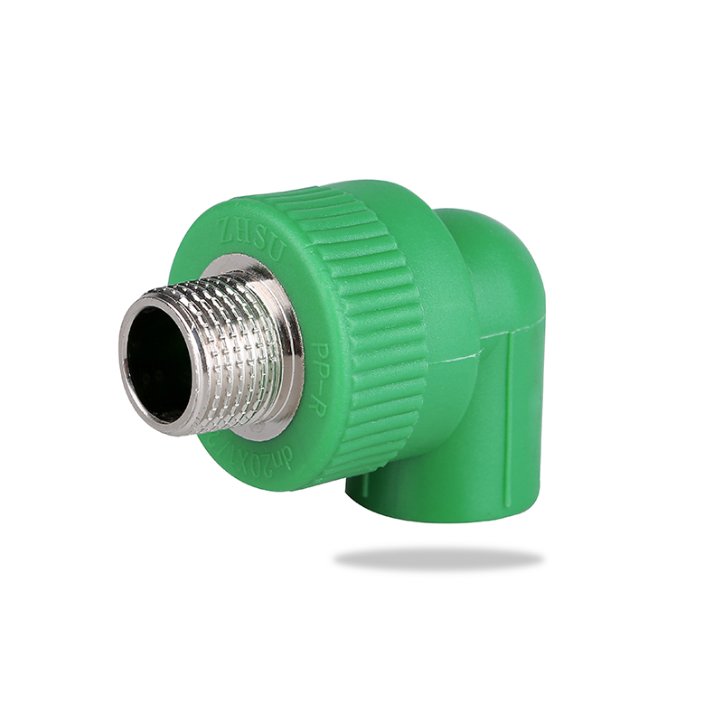
| Building water supply (PPR) | 90° (LR where possible) | Space constraints in wall/ceiling voids |
| Underground gas distribution (HDPE) | 45° preferred; 90° (LR) where needed | Lower pressure drop; long fusion-welded runs |
| HVAC ductwork and air handling | 45° or LR 90° | Flow efficiency critical; noise reduction |
| Industrial process piping (high flow) | 45° | Minimize pump energy; reduce elbow erosion |
| Chemical processing (corrosive media) | 45° | Reduce turbulence and localized wear |
| Drainage and wastewater | 45° (gravity systems) | Maintain self-cleaning velocity; avoid solids buildup |
| Compact equipment/machine piping | 90° (SR) | Minimum footprint; space takes priority |
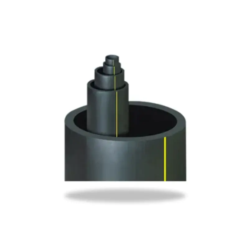
For underground gas pipeline systems specifically, HDPE natural gas piping systems are typically routed with gradual horizontal bends where terrain permits, using electrofusion 45-degree fittings at transitions to minimize pressure drop across distribution networks. Our HDPE fittings for industrial piping systems cover the full range of elbow angles, SDR grades, and connection methods needed for gas and water infrastructure projects.
When to Use Two 45-Degree Elbows Instead of One 90-Degree Elbow
Substituting two 45-degree elbows with a short pipe section between them for a single 90-degree elbow is a standard engineering technique worth applying deliberately rather than by default. The pressure drop of the combination—two separate 45-degree transitions—is comparable to a long-radius 90-degree elbow and significantly lower than a standard short-radius 90-degree elbow.
The connecting pipe section between the two 45-degree elbows serves an additional hydraulic function: it allows the turbulent flow from the first bend to partially recover before entering the second bend. The greater the separation distance, the more complete that recovery. As a practical rule, a separation of at least five pipe diameters between the two elbows ensures the flow profile is substantially re-established before the second bend, minimizing the compounding effect of back-to-back fittings.
This two-45 configuration is particularly effective in pump inlet and outlet piping, where maintaining uniform velocity distribution at the pump flange improves pump efficiency and reduces cavitation risk. It is also common in suction lines for centrifugal pumps, metering stations, and any application where the velocity profile entering a sensitive piece of equipment needs to be as uniform as possible.
The trade-off is always space. The two-45 configuration requires a diagonal run that adds horizontal offset to the layout. In open-plan mechanical rooms or ceiling spaces, this is rarely a problem. In dense equipment racks or congested wall chases, the single 90-degree fitting wins by necessity.
Decision Checklist: 90° or 45° Elbow?
Use the following checklist to evaluate elbow choice systematically for any new installation or system modification:
- Is space severely constrained? If the direction change must fit within a fixed structural void or equipment bay — use 90°.
- Is flow efficiency or energy consumption a priority? If pump operating cost, pressure budget, or flow uniformity matters — use 45° or two 45° in series.
- Does the fluid carry abrasive particles or is erosion a concern? Use 45° to reduce impact velocity and extend elbow service life.
- Is noise or vibration a system concern? Use 45° or LR 90° to minimize turbulence-induced vibration at direction changes.
- Is the system plastic pipe (PPR or HDPE) subject to thermal cycling? A layout with 45-degree offsets provides better thermal expansion absorption than a rigid 90-degree grid.
- Are multiple elbows in close sequence? Use 45° or LR 90° to limit cumulative pressure loss, and separate consecutive fittings by at least five pipe diameters where possible.
- Is this a gravity drainage or wastewater system? Use 45° to maintain velocity and prevent solids settling in horizontal runs.
The simplest summary: when space drives the decision, use 90°; when system performance drives the decision, use 45°. In many real installations, both angles appear in the same system—each assigned to the location where its specific advantage is most needed.